Measuring Dissolved Oxygen
Dissolved Oxygen Measurement Methods
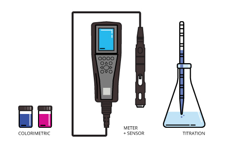
There are three methods available for measuring dissolved oxygen concentrations. Modern techniques involve either an electrochemical or optical sensor. The dissolved oxygen sensor is attached to a meter for spot sampling and laboratory applications or to a data logger, process monitor or transmitter for deployed measurements and process control.
The colorimetric method offers a basic approximation of dissolved oxygen concentrations in a sample. There are two methods designed for high-range and low-range dissolved oxygen concentrations. These methods are quick and inexpensive for basic projects, but limited in scope and subject to error due to other redoxing agents that may be present in the water 27.
The traditional method is the Winkler titration. While this method was considered the most accurate and precise for many years, it is also subject to human error and is more difficult to execute than the other methods, particularly in the field 27. The Winkler method now exists in seven modified versions which are still used today 27.
Measuring Dissolved Oxygen by the Sensor Method
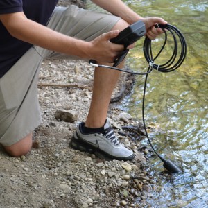
The most popular method for dissolved oxygen measurements is with a dissolved oxygen meter and sensor. While the general categories of dissolved oxygen sensors are optical and electrochemical, electrochemical sensors can be further broken down into polarographic, pulsed polarographic and galvanic sensors. In addition to the standard analog output, several of these dissolved oxygen sensor technologies are available in a smart sensor platforms with a digital output.
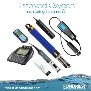
A dissolved oxygen sensor can be used in the lab or in the field. DO sensors can be designed for biochemical oxygen demand (BOD) tests, spot sampling or long-term monitoring applications. A dissolved oxygen meter, water quality sonde or data logging system can be used to record measurement data taken with a DO sensor.
As dissolved oxygen concentrations are affected by temperature, pressure and salinity, these parameters need to be accounted for 7. These compensations can be done manually or automatically with a dissolved oxygen meter or data logging software. Temperature is generally measured by a thermistor within the sensor and is acquired by the meter or data logger without prompting. Many DO meters include an internal barometer, and data logging systems can be set up with an external barometer or water level sensor for pressure measurements. Barometric pressure can also be manually input as altitude, true barometric pressure or corrected barometric pressure. Salinity can be measured with a conductivity/salinity sensor and automatically compensated for, or approximated and manually input as 7:
Fresh water | < 0.5 ‰ (PPT or parts per thousand) |
Brackish water | 0.5-30 ‰ |
Seawater | 33-37 ‰ |
Saline water | 30-50 ‰ |
Brine | > 50 ‰ |
Calibration and operating procedures can vary between models and manufacturers. An instruction manual should be referenced during the measurement and calibration processes.
Optical Dissolved Oxygen Sensors
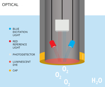
Optical dissolved oxygen sensors measure the interaction between oxygen and certain luminescent dyes. When exposed to blue light, these dyes become excited (electrons gaining energy) and emit light as the electrons return to to their normal energy state 12. When dissolved oxygen is present, the returned wavelengths are limited or altered due to oxygen molecules interacting with the dye. The measured effect is inversely proportional to the partial pressure of oxygen 5. While some of these optical DO sensors are called fluorescent sensors 10, this terminology is technically incorrect. These sensors emit blue light, not ultraviolet light, and are properly known as optical or luminescent DO sensors 11. Optical dissolved oxygen sensors can measure either the intensity or the lifetime of the luminescence, as oxygen affects both 23.
An optical DO sensor consists of a semi-permeable membrane, sensing element, light-emitting diode (LED) and photodetector 3. The sensing element contains a luminescent dye that is immobilized in sol-gel, xerogel or other matrix 23. The dye reacts when exposed to the blue light emitted by the LED 3. Some sensors will also emit a red light as a reference to ensure accuracy 5. This red light will not cause luminescence, but simply be reflected back by the dye 7. The intensity and luminescence lifetime of the dye when exposed to blue light is dependent on the amount of dissolved oxygen in the water sample 23. As oxygen crosses the membrane, it interacts with the dye, limiting the intensity and lifetime of the luminescence 3. The intensity or lifetime of the returned luminescence is measured by a photodetector, and can be used to calculate the dissolved oxygen concentration.
The concentration of dissolved oxygen (as measured by its partial pressure) is inversely proportional to luminescence lifetime as shown by the Stern-Volmer equation5:
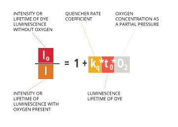
Io /I = 1 + kq * t0 * O2
Io= Intensity or lifetime of dye luminescence without oxygen
I = Intensity or lifetime of luminescence with oxygen present
kq = Quencher rate coefficient
t0 = Luminescence lifetime of the dye
O2 = oxygen concentration as a partial pressure
This equation accurately applies at low dissolved oxygen concentrations 7. At high concentrations, this measurement is non-linear 23. This nonlinearity comes from the way oxygen interacts in the polymer matrix of the dye 25. In polymers, dissolved gasses show a negative deviation from Henry’s Law (which determines partial pressure) 25. This means that higher concentrations, oxygen solubility in the dye matrix will follow the modified Stern-Volmer equation24:
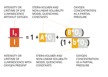
Io /I = 1 + AO2 + BO2/(1+bO2 )
Io = Intensity or lifetime of dye luminescence without oxygen
I = Intensity or lifetime of luminescence with oxygen present
A, B, b = Stern-Volmer and non-linear solubility model quenching constants
O2 = oxygen concentration as a partial pressure
The use of this equation requires inputting pre-determined sensor constants (Io, A, B, b) which are specific to each new or replacement sensor cap 5.
Optical dissolved oxygen sensors tend to be more accurate than their electrochemical counterparts, and are not affected by hydrogen sulfide or other gasses that can permeate an electrochemical DO membrane 7. They are also capable of accurately measuring dissolved oxygen at very low concentrations 3.
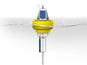
Optical DO sensors are ideal for long-term monitoring programs due to their minimal maintenance requirements. They can hold a calibration for several months and exhibit little (if any) calibration drift 5. These dissolved oxygen sensors also do not require any warm-up time or stirring when taking a measurement 7. Over a long period of time, the dye degrades and the sensing element and membrane will need to be replaced, but this replacement is very infrequent compared to electrochemical sensor membrane replacement. Luminescence lifetime-measuring sensors are less affected by dye degradation than intensity-measuring sensors, which means that they will maintain their accuracy even with some photodegradation 24.
However, optical dissolved oxygen sensors usually require more power and take 2-4 times longer to acquire a reading than an electrochemical DO sensor 7, 14. These sensors are also heavily dependent on temperature 7. Luminescence intensity and lifetime are both influenced by ambient temperature 23, though most sensors will include a thermistor to automatically correct the data 12.
Electrochemical Dissolved Oxygen Sensors
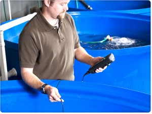
Electrochemical dissolved oxygen sensors can also be called amperometric or Clark-type sensors. There are two types of electrochemical DO sensors: galvanic and polarographic. Polarographic dissolved oxygen sensors can be further broken down into steady-state and rapid-pulsing sensors. Both galvanic and polarographic DO sensors use two polarized electrodes, an anode and a cathode, in an electrolyte solution 7. The electrodes and electrolyte solution are isolated from the sample by a thin, semi-permeable membrane.
When taking measurements, dissolved oxygen diffuses across the membrane at a rate proportional to the pressure of oxygen in the water 7. The dissolved oxygen is then reduced and consumed at the cathode. This reaction produces an electrical current that is directly related to the oxygen concentration 7. This current is carried by the ions in the electrolyte and runs from the cathode to the anode 19. As this current is proportional to the partial pressure of oxygen in the sample 15, it can be calculated by the following equation:
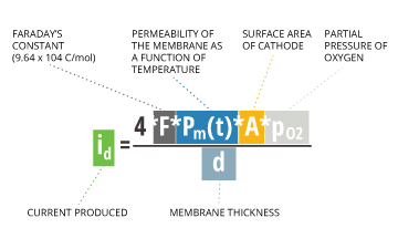
id = (4 * F * Pm(t) * A * pO2) / d
id = current produced
F = Faraday’s constant = 9.64×10^4 C/mol
Pm(t) = permeability of the membrane as a function of temperature
A = surface area of cathode
pO2 = partial pressure of oxygen
d = membrane thickness
Typical currents produced by oxygen reduction are around 2 uAmps 16.
If measurements are being done in a lab or still water, it is necessary to stir galvanic and polarographic DO sensors in solution. This measurement method is dependent on flow due to the consumption of the oxygen molecules 7. When the oxygen is consumed, the sensors can produce an artificially low DO reading in no-flow situations 7. Electrochemical dissolved oxygen sensors should be stirred in the sample until the dissolved oxygen readings no longer increase.
Polarographic Dissolved Oxygen Sensors
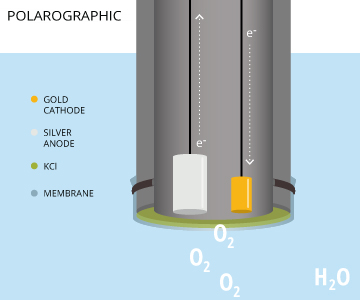
A polarographic DO sensor is an electrochemical sensor that consists of a silver anode and a noble metal (such as gold, platinum or infrequently, silver) cathode in a potassium chloride (KCl) solution 8. When the instrument is turned on, it requires a 5-60 minute warm-up period to polarize the electrodes before calibrating or measuring. The electrodes are polarized by a constant voltage (between 0.4 V and 1.2 V is required to reduce oxygen) from the cathode to the anode 8). As electrons travel in the opposite direction of a current, the anode becomes positively polarized and the cathode becomes negatively polarized 14. This polarization occurs as electrons travel from the anode to the cathode via an internal wire circuit 19. When oxygen diffuses across the membrane, the molecules are reduced at the cathode, increasing the electrical signal 7. The polarizing potential is held constant while the sensor detects changes in the current caused by the dissolved oxygen reduction 7. The more oxygen that passes the the membrane and is reduced, the greater the electrical current read by the polarographic DO sensor.
This is a two-part reaction – the oxidation of the silver anode and the reduction of the dissolved oxygen. These reactions occur as follows:
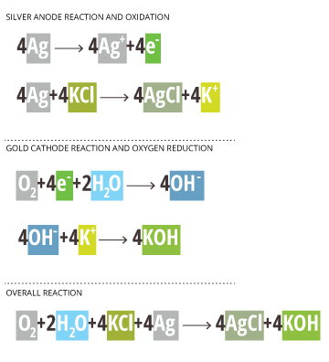
Ag – silver anode
KCl and H2O – potassium chloride solution
Au/Pt – gold or platinum cathode *inert electrode – does not participate*
Silver Anode Reaction and Oxidation
4Ag —-> 4Ag+ +4e–
4Ag+ 4KCl —-> 4AgCl + 4K+
Gold Cathode Reaction and Oxygen Reduction
*The Au/Pt cathode is inert and only passes electrons; it does not participate in the reaction* 18
O2 + 4e– + 2H2O —-> 4OH–
4OH– + 4K+ —-> 4KOH
Overall Reaction
O2 + 2H2O + 4KCl + 4Ag —-> 4AgCl + 4KOH
The gold/platinum cathode is left out of the reaction equation as it does not interfere with nor participate in the reaction 18. In a polarographic dissolved oxygen sensor, the role of the cathode is to accept and pass on electrons from the anode to the oxygen molecules. In order for oxygen to acquire the electrons, the oxygen reduction reaction must occur at the cathode’s surface 13. The electrons passed from the silver anode to the cathode via an internal circuit are used to reduce the oxygen molecules to hydroxide ions at the cathode’s surface, producing a current. This current is proportional to oxygen consumed, and thus to the partial pressure of oxygen in the sample 15.
The silver anode is oxidized during this process as it gives up its electrons to the reduction reaction, but the oxidation only occurs when measurements are being taken 7. This reaction is noticeable as the anode darkens (AgCl coating). As the oxidized coating accumulates, the sensor’s performance will degrade 7. This will be clear not only visually when looking at the electrode, but when using the dissolved oxygen sensor. Readings will be unusually low, will not stabilize, or the sensor will not calibrate 7. When this occurs, the electrodes can be cleaned to restore sensor performance 7. Electrode maintenance should be far less frequent than membrane replacement, which is based on application 7.
Pulsed Polarographic Dissolved Oxygen Sensors
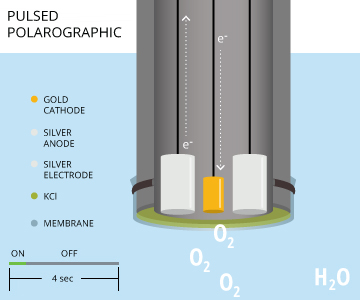
Pulsing polarographic dissolved oxygen sensors remove the need to stir a sample for accuracy when measuring dissolved oxygen. A rapid-pulse DO sensor is similar to a steady-state polarographic DO sensor as both utilize a gold cathode and silver anode. Both steady-state and rapid-pulse sensors also measure dissolved oxygen by producing a constant voltage to polarize the electrodes 7. However, these pulsing polarographic DO sensors turn on and off approximately every four seconds, allowing the dissolved oxygen to replenish at the membrane and cathode surface 7. This replenishing creates a flow dependence of almost zero 7. In order to consistently polarize and de-polarize the electrodes for these short time periods, a pulsing polarographic DO sensor includes a third, silver reference electrode, separate from the silver anode 7. The electrochemical reaction (silver oxidation and oxygen reduction) remains the same.
As rapid-pulse polarographic sensors reduce flow dependence when taking DO measurements, the water sample does not need to be stirred when using this sensor 7.
Galvanic Dissolved Oxygen Sensors
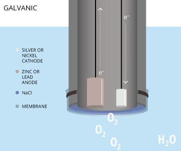
The final electrochemical dissolved oxygen sensor is galvanic. In a galvanic dissolved oxygen sensor, the electrodes are dissimilar metals. Metals have different electropotentials based on their activity series (how readily they give or accept electrons) 17. When placed in an electrolyte solution, the potential between dissimilar metals causes them to self-polarize 16. This self-polarization means that a galvanic DO sensor does not require any warm-up time. In order to reduce oxygen without an external applied potential, the difference in potential between the anode and the cathode should be at least 0.5 volts 16.
The anode in a galvanic dissolved oxygen sensor is usually zinc, lead or another active metal while the cathode is silver or another noble metal 3. The electrolyte solution can be sodium hydroxide, sodium chloride, or another inert electrolyte 8,27. The electrochemical reaction in galvanic DO sensors is very similar to the reaction in polarographic DO sensors, but without the need for a separate, constant potential. The dissimilar electrodes self-polarize, with the electrons traveling internally from the anode to the cathode 7. The cathode remains inert, serving only to pass on electrons and it does not interfere in the reaction 20. Thus the anode is oxidized and oxygen is reduced at the surface of the cathode. These reactions occur as follows:
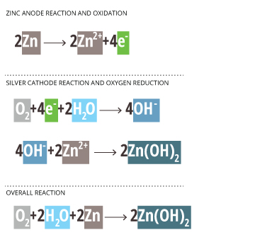
Zn/Pb – zinc or lead anode
NaCl and H2O – sodium chloride solution
Ag – silver cathode *inert electrode, does not react*
Zinc Anode Reaction and Oxidation
2Zn —-> 2Zn2+ + 4e–
Silver Cathode Reaction and Oxygen Reduction
*The Ag cathode is inert and only passes electron without participating in the reaction* 18
O2 + 4e– + 2H2O —-> 4OH–
4OH– + 2Zn2+ —-> 2Zn(OH)2
Overall Reaction
O2 + 2H2O + 2Zn —-> 2 Zn(OH)2
As in the polarographic dissolved oxygen sensor reaction, the cathode is left out of the equation because it is an inert electrode 18. The silver cathode accepts electrons from the anode and passes them on to the oxygen molecules. This transaction occurs at the cathode’s surface 8. The current produced by the reduction of oxygen is proportional to the partial pressure of oxygen in the water sample 15.
The zinc hydroxide that is produced by these reactions is precipitated out into the electrolyte solution. This precipitate is visible as a white solid at the tip of the sensor 7. This precipitate neither coats the anode nor consumes the electrolyte, and thus does not affect the sensor’s performance until the quantity becomes excessive. If this happens, it may interfere with the ions’ ability to carry current between the cathode and the anode 22. When the sensor output is unusually low or the readings do not stabilize, it is necessary to replace the electrolyte solution 7.
As the electrodes in a galvanic DO sensor are self-polarizing, the oxidation of zinc will continue to occur even when the instrument is not in use 7. That being said, a galvanic dissolved oxygen sensor will operate efficiently even as the zinc anode is consumed, though it may need to be replaced more frequently than a polarographic DO sensor 7.
Measuring Dissolved Oxygen by the Colorimetric Method
There are two variations of dissolved oxygen analysis by the colorimetric method. These are known as the indigo carmine method and the rhodazine D method. Both variations use colorimetric reagents that react and change color when reacted with oxygen in the water 6. These interactions are based on the oxidation of the reagent, and the extent of the color change is proportional to the dissolved oxygen concentration 27. Measuring dissolved oxygen by a colorimetric methods can be done with a spectrophotometer, colorimeter or a simple comparator. Using a spectrophotometer or a colorimeter produces more accurate results, while comparison against a comparator such as a color wheel or color block is quick and inexpensive. However, as the human eye is not objective, this can result in some inaccuracy 6.
Indigo Carmine
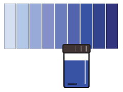
The indigo carmine method can be used for measuring dissolved oxygen concentrations between 0.2 and 15 ppm (mg/L). This method produces a blue color, the intensity of which is proportional to the dissolved oxygen concentration 31. Ferric iron, ferrous iron, nitrite and sodium hydrosulfite can interfere with this method 27. In addition, reagents should be kept out of bright light as prolonged exposure can deteriorate the indigo carmine 32. However, this method is not affected by temperature, salinity or dissolved gases 28. Low-range tests are time-dependent and should be analyzed within 30 seconds, while high-range tests require a two-minute processing time 31.
Rhodazine D
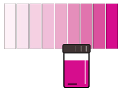
The rhodazine D method is used to determine very low dissolved oxygen concentrations. Able to measure in the parts per billion (ppb), rhodazine D reagents react with dissolved oxygen to form a deep rose-colored solution 30. This colorimetric method is not affected by salinity or dissolved gases such as sulfide that can be present in the water sample 28. However, oxidizing agents such as chlorine, ferric iron and cupric copper can interfere and cause higher DO readings 29. Other causes of error are polysulfides, hydroquinone/benzoquinone, and boron and hydrogen peroxide (if both are present) 29. In addition, sample color and turbidity can affect the accuracy of the readings 29. This method is time-dependent, as the analysis must be made within 30 seconds of mixing the reagent 30.
Measuring Dissolved Oxygen by the Titrimetric Method
The titrimetric method for dissolved oxygen analysis is known as the Winkler method. This method was developed by L.W. Winkler, a Hungarian chemist, in 1888 4. Also known as the iodometric method, the Winkler method is a titrimetric procedure based on the oxidizing property of dissolved oxygen 26. This method has long been the standard for accuracy and precision when measuring dissolved oxygen27.
Winkler Method
Samples are collected, fixed and titrated, either in the field or in a lab. The sample should be fixed with the reagents as soon as possible to prevent oxygen levels from shifting due to agitation or atmospheric contact. The Winkler method requires a specific bottle, known as a BOD bottle, which is designed to seal without trapping air inside 1. Today, the reagents required can come in pre-measured packets for greater accuracy and ease of use 33. When using this method, the amount of titrant needed to complete the reaction is proportional to the dissolved oxygen concentration of the sample 6.
While the Winkler method is still a recognized standard for analyzing dissolved oxygen, several concerns have been identified 27. This method is subject to human error, inaccuracies, sample contaminants and interferences 6. In addition, titrations can be time-consuming, and cumbersome in the field 7.
Modified Winkler Methods
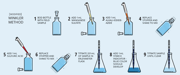
Now seven modified Winkler methods exist, each created to respond to a different issue (such as an interfering contaminant) 27. The most popular of these is the Azide-Winkler method, as it addresses the issues with iodine present in the original method 1. However, the rest of the modified methods create a new concern – these methods require prior knowledge of the sample (such as other elements present) in order to make the appropriate choice of method 27.
If one has the time and the inclination, the titrimetric method for dissolved oxygen analysis can be accurate and precise. However, new technologies have created dissolved oxygen sensors that are easier and quicker to use and can be just as accurate in most applications 27.
Cite This Work
Fondriest Environmental, Inc. “Measuring Dissolved Oxygen.” Fundamentals of Environmental Measurements. 7 Jan. 2014. Web. < https://www.fondriest.com/environmental-measurements/measurements/measuring-water-quality/dissolved-oxygen-sensors-and-methods/>.


