
Solinst Model 301 WLTS: Works Well Under Pressure
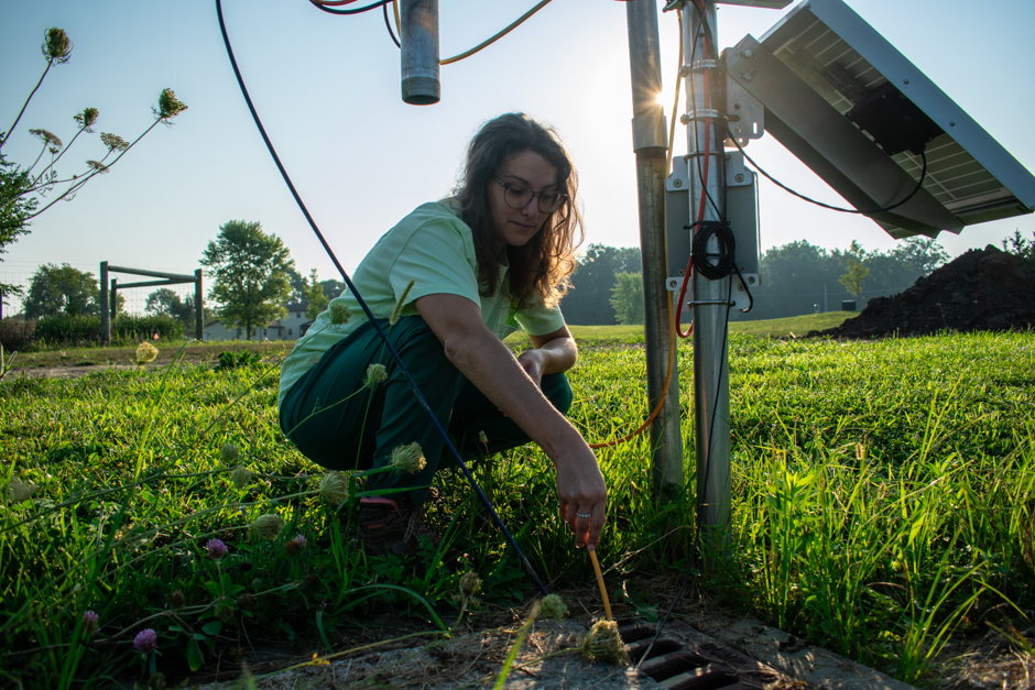 Science team deploying the WLTS in the pond weir after integration with the X3 data logger. (Credit: Emma Jones)
From an already successful line of water level and temperature loggers comes the new Water Level Temperature Sensor (WLTS) by Solinst, Inc. Unlike other water level measurement devices offered by Solinst, the WLTS is designed to integrate with 3rd party data loggers in industrial and environmental monitoring systems using digital communication protocols.
Sensors that can be easily integrated with external devices allow for the addition of stable and continuous water level and temperature measurements to existing monitoring networks.
While some water level sensors use pressure transducers to determine water level, the WLTS utilizes a hydrostatic level transmitter to record water levels and a platinum resistance temperature detector for temperature compensation. The WLTS is designed to last during longer deployments with a stainless steel sensor housing and double O-ring seals to prevent leaks.
Accurate water level data is needed in a variety of applications such as groundwater wells, rivers, lakes, reservoirs, seawater, wastewater, industrial, stormwater, and landfills.
In order to meet the demands of all applications, the WLTS is available in a variety of pressure ranges (see specifications) and cable lengths (up to 300m).
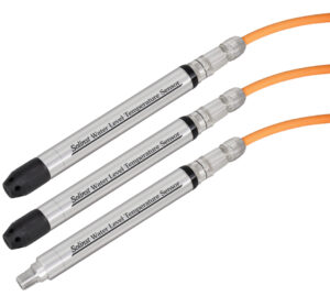
The New Solinst Model 301 Water Level Temperature Sensors with and without the nosecone. (Credit: Solinst)
| Solinst General WLTS Specifications | |
|---|---|
| Size | 22 mm x 192 mm (7/8″ x 7.55″) |
| Weight | 173 grams (6.1 ounces) |
| Wetted Materials | Delrin®, Viton®, 316L stainless steel, Hastelloy, Polyurethane (TPU boot) |
| Digital Communication | Modbus and SDI-12 |
| Interface Connector | 4-Conductor |
| Power Consumption | Max 2mA in idle, 10mA while reading sensor |
| WLTS Level Sensor Specifications | |
| Available Ranges | M5, M10, M20, M30, M100, M200 (meters) |
| Accuracy | ± 0.05% FS |
| Resolution | 0.0006% FS |
| Material | Piezoresistive Silicon with Hastelloy® sensor (Absolute or Gauged) |
| Normalization | Automatic Temperature Compensation |
| Temp. Comp. Range | 0°C to 50°C |
| WLTS Temperature Sensor Specifications | |
| Accuracy | ± 0.05ºC |
| Resolution | 0.003°C |
| Operating Temperature | -20°C to 80°C |
| Material | Platinum Resistance Temperature Detector (RTD) |
| Response Time | 1~2 minutes |
Non-vented (Absolute) vs Vented (Gauge) Level Measurements
There are two ways that water level can be determined with the WLTS: either via absolute or gauge pressure. Deciding which pressure sensor is best for the chosen application typically depends on site restrictions.
Absolute sensors measure the pressure of fluid above the zero point of the sensor (as indicated on the illustration below) plus atmospheric pressure. In contrast, gauge sensors measure the pressure of fluid above the zero point minus atmospheric pressure with the use of the vent tube. Gauge pressure is also referred to as vented pressure when a vent tube is utilized.
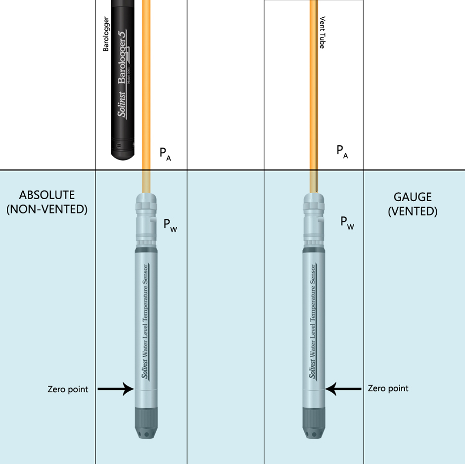
A diagram of an absolute and gauge pressure sensor deployment showing how the pressure of air (PA) is removed from water level measurements either by use of a Solinst Barologger or a vent tube in order to get compensated level data or hydraulic head. (Credit: Fondriest Environmental)
In cases where a vent tube cannot be used in the setup due to locking caps and seals that do not vent to the atmosphere, a Barologger or another method of compensating for barometric pressure must be used. In this application, a barometric pressure logger will need to be deployed within a 20-mile radius and data will be applied to the level sensor reading by the user in post-processing. .
For deployments that can accommodate the vent tube in the setup, barometric compensation is done automatically, as the tube is still vented to the atmosphere and not obstructed.
| Communication Cable Specifications | |
| Length | Up to 300 m |
| Diameter | Cable: 8 mm (0.32″) Connector: 20 mm (0.79″) |
| Wetted Materials | Polyurethane, Nickel plated Brass, Viton |
| Vent Tube Moisture Protection | Built-in hydrophobic filters at sensor connection and plug at surface |
| Operating Temperature | -20ºC to 80ºC |
| Max. Bend Radius | 25 mm (1″) |
Versatility in Design for All Applications
Designed for integration, the WLTS is suitable for use with commercial data loggers and controllers. Digital communication protocols include MODBUS (serial communication via RS-485) and SDI-12 (serial data interface, 1200 baud rate).
The pressure sensor is made of piezoresistive silicon with Hastelloy® enclosed in a 316L stainless steel body to withstand long-term deployments and continuous data collection.
With both large-scale and smaller applications in mind, the innovative hydrophobic filter used in the vented cable assemblies eliminates the need for desiccant replacements that can be time-consuming and costly.
Required Equipment and Software
In addition to the sensor and cable, a WLTS USB programming cable is required to set up the sensor, run diagnostics, and upgrade firmware. The WLTS PC Software Utility, offered for free on Solinst’s website, is also needed to perform the aforementioned actions.
Solinst offers various guides and videos that can assist with the setup and use of the WLTS. As with other sensors, it is recommended to setup and test the sensor prior to deployment in a lab or office setting. Similarly, with any integrated system, it is best to work through any potential issues before deployment, rather than at the install site.
View the Solinst YouTube channel here: https://www.youtube.com/@SolinstCanada/
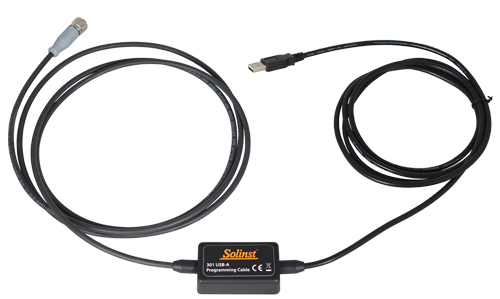
The WLTS programming cable used for setup, diagnostics and updates. (Credit: Solinst)
Setup and Deployment at the Field Station
The complete setup deployed at the field station includes the Solinst WLTS sensor, a vented cable, and a programming cable. The cable was wired onto a vented version of the NexSens Field Wireable Plug. The NexSens UW connection enables the WLTS to interface with NexSens X-Series Data Logger.
NexSens engineers developed a simple SDI-12 script using the CONNECT software so the logger could recognize the sensor when connected via the UW-plug. Using the Solinst programming cable and Windows-based WLTS PC Software Utility, the communication protocol was set to SDI-12 and the digital address was updated to match the script. Once it was established that the setup was communicating, it was time to take it out to the field station for deployment.
Fondriest Environmental Field Testing Analysis
The science team thought the new ready-to-integrate Solinst Water Level and Temperature Sensor would be a good addition to the existing monitoring network at the field station. Once the team had the sensor programmed and prepared for deployment, it was taken out to the site, plugged into the data logger, and lowered down into the pond weir to collect water level and temperature data.
After the installation was complete, data was immediately viewable on the field station’s WQData LIVE portal and was found to be comparable to an existing level logger at the site. Solinst recommends checking that deployed sensors are reading accurately by comparing the readings with a manual water level meter on site.
Overall, the science team found the new WLTS was easy to integrate with the NexSens data logger. Additionally, the team noted that the cable and sensor seem very robust compared to other sensor cables they have seen due to the strong materials used. Satisifed with the ease of deployment and quality of the data collected by the WLTS, the sensor will remain deployed at the field station for the foreseeable future.
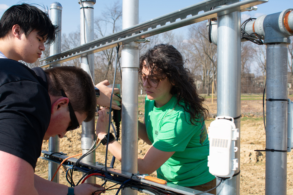
The Science Team connects the Solinst WLTS with the X-series logger and monitoring station near the pond at the Field Station. (Credit: Emma Jones)


0 comments